7편 Let’s go~^^
아래 모델은 반경 방향과 축 방향으로 선형 온도 벡터가 적용된 두꺼운 솔리드 실린더입니다. y축의 실린더 내부 A 지점에서의 Direct stress σzz 값을 linear static 해석을 통해 알아 볼 수 있습니다.
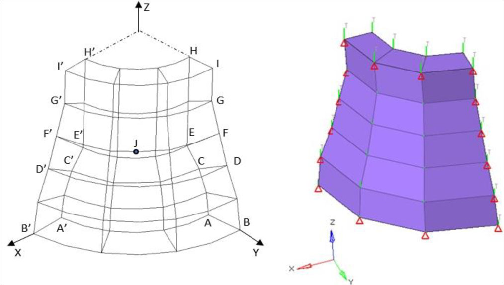
Figure 0070-1: FE-Model with Boundary Conditions and Loadcases
Benchmark Model
모델 구성은 Second order (Hexahedral, Penta, Tetra) elements를 이용한 각 타입별 Coarse & Fine Mesh로 생성되어 있으며, T°C = (x2 + y2)1/2 + z의 선형 온도 벡터는 실린더의 중심에서 반경 방향과 축 방향으로 적용되어져 있습니다. 이 모델은 실린더의 1/4만 고려된 모델 입니다. 위의 그림을 참고 하시기 바랍니다.
| The material properties are: |
| MAT1 Isotropic |
| Young’s Modulus 210 x 10^3 MPa |
| Poisson’s Ratio 0.3 |
| Coefficient of Thermal Expansion 2.3 x 10^-4/°C |
Linear Static Analysis Results
Viewing the Result
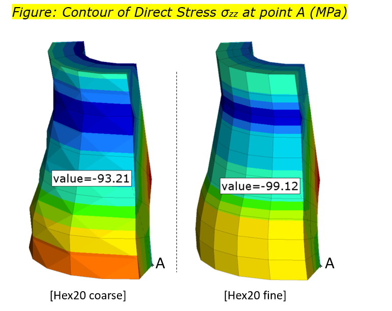 All results are normalized with the target value σzz (-105MPa)
아래표의 해석 결과 값을 참조 하시기 바랍니다.
| Direct Stress σzz at Point A Normalized with the (MPa) Value |
| Solid Hexahedral: | ||
| Hex20 coarse | -93.21 | 1.126488574 |
| Hex20 fine | -99.12 | 1.059322034 |
| Solid Wedges: | ||
| Penta15 coarse | -100.3 | 1.046859422 |
| Penta15 fine | -103.7 | 1.012536162 |
| Solid Tetrahedral: | ||
| Tetra10 coarse | -91.97 | 1.141676634 |
| Tetra10 fine | -98.68 | 1.064045399 |
Model Files
The model files used in this example include
install_directory/demos/hwsolvers/optistruct/verification
/LE11Hex20C.fem
/LE11Hex20F.fem
/LE11Pyr15C.fem
/LE11Pyr15F.fem
/LE11Tet10C.fem
/LE11Tet10F.fem
Reference
NAFEMS Ltd, The Standard NAFEMS BENCHMARKS TNSB Rev. 3, NAFEMS Ltd, Scottish Enterprise Technology Park, Whitworth Building, East Kilbride, Glasgow, United Kingdom, 1990.

|

|